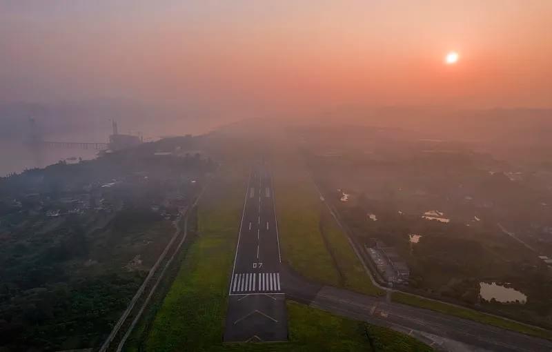
Runway Visual Range (RVR) is the backbone of aviation safety, defining the maximum distance pilots can clearly see runway markings or lights under current weather conditions. For airports worldwide—from small regional hubs to major international terminals—accurate RVR data is non-negotiable, as it directly dictates whether aircraft can safely take off, land, or taxi, especially when visibility drops due to fog, rain, snow, or darkness. Without reliable RVR measurements, airports face catastrophic accident risks, costly operational delays, and non-compliance with global aviation regulations—making RVR systems a critical investment for all aviation stakeholders.
1. Why Runway Visual Range (RVR) Matters for Modern Aviation
In aviation, where split-second decisions determine safety, Runway Visual Range (RVR) acts as a silent guardian. Unlike general meteorological visibility— which measures horizontal visibility over open terrain (e.g., fields, roads)—RVR is tailored to the runway environment. It accounts for runway lighting intensity, terrain obstacles, and local weather patterns to deliver a precise, runway-specific visibility metric. This distinction makes RVR far more relevant to flight operations than standard visibility readings.
A 2023 report from the International Civil Aviation Organization (ICAO) highlights RVR’s importance: 42% of runway-related incidents occur in low-visibility conditions, and 78% of those incidents link to inaccurate or unavailable RVR data. For commercial airports handling thousands of daily flights, a single hour of RVR-related delays can cost over $150,000 in fuel, staff overtime, and passenger compensation. Small regional airports face even greater stakes—unreliable RVR can force temporary closures, cutting off critical communities from air travel.
Beyond safety and efficiency, RVR is a regulatory mandate. Every major aviation authority—including ICAO, the U.S. Federal Aviation Administration (FAA), and the European Union Aviation Safety Agency (EASA)—requires airports to measure and report RVR in low-visibility conditions. Non-compliance leads to fines, operational restrictions, or even revocation of an airport’s operating license. For example, an airport in Brazil was fined in 2021 after a runway-adjacent tree reduced threshold RVR by 200 meters, causing multiple missed approaches.

2. Defining Runway Visual Range (RVR): Units, Segments, and Key Distinctions
To leverage RVR effectively, it’s critical to understand its official definition, measurement units, and how it differs from other visibility metrics.
2.1 The Official Definition of RVR
ICAO—the global authority on aviation standards—defines Runway Visual Range (RVR) as:
“The maximum distance over which the pilot of an aircraft on the centerline of a runway can see the runway surface markings or the lights delineating the runway or identifying its threshold.”
In simple terms, RVR answers a pilot’s most urgent question: “How far down the runway can I see clearly enough to land or take off?” This is not a subjective estimate—it’s a data-driven value calculated using specialized runway-side equipment.
2.2 Units of Measurement for RVR
RVR uses two primary units, depending on regional regulations:
- Meters (m): The ICAO-standard unit used by most international airports. Common RVR thresholds include 550 m (Category I operations), 350 m (Category II), and 200 m (Category IIIa).
- Feet (ft): Used primarily in the U.S. and a handful of other countries. Equivalent thresholds are 1,800 ft (Category I), 1,200 ft (Category II), and 700 ft (Category IIIa).
Airports must align with local requirements: U.S. airports report RVR in feet to comply with FAA rules, while European airports use meters for EASA compliance.
2.3 RVR vs. Meteorological Visibility: Critical Differences
A common misconception is that RVR and meteorological visibility (often called “prevailing visibility”) are interchangeable. Confusing the two can lead to dangerous errors. Below is a breakdown of their key differences:
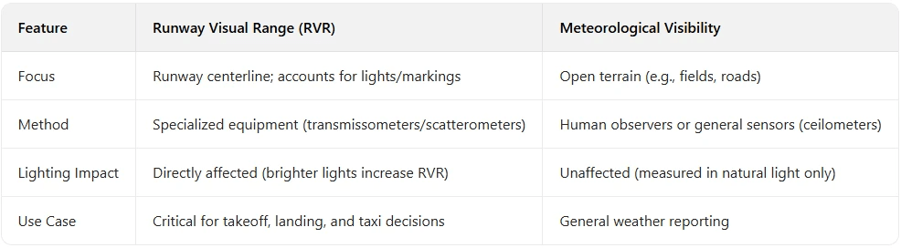
Example: On a foggy morning, prevailing visibility over open terrain might be 1,000 meters, but RVR could be 500 meters (if fog is denser over the runway) or 700 meters (if runway lights are at maximum intensity). For pilots, only the RVR value matters—it reflects the actual visibility they’ll experience on the runway.
2.4 RVR Segments: Threshold, Midpoint, and Rollout
To give pilots comprehensive visibility data, RVR is measured at three key runway segments:
- Threshold RVR: Measured at the runway threshold (start of the landing area). This is the most critical segment for approaching pilots, as it shows visibility when crossing the threshold.
- Midpoint RVR: Measured at the runway’s midpoint. Helps pilots assess visibility during the middle of the landing roll.
- Rollout RVR: Measured 1,000 feet (300 meters) from the runway’s far end. Ensures pilots can see far enough to stop safely after landing.
Most airports prioritize threshold RVR, but midpoint and rollout RVR are mandatory for Category II and III operations (low-visibility landings). The FAA requires Category II runways to report threshold and midpoint RVR, while Category III runways must report all three segments.
3. How Runway Visual Range (RVR) Is Measured: Equipment and Technology
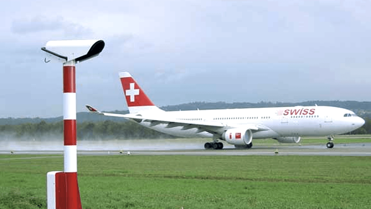
Accurate RVR measurements depend on specialized equipment designed to withstand harsh weather and deliver real-time data. The two primary systems are transmissometers and scatterometers—each with unique strengths, limitations, and use cases.
3.1 Transmissometers: The Gold Standard for RVR
Transmissometers are the most widely used RVR measurement tools, favored globally for their accuracy and compliance with ICAO, FAA, and EASA standards. They work by emitting a light beam across the runway and measuring how much light is transmitted (not absorbed or scattered) by air particles (fog, rain, snow, dust). Less transmitted light means lower RVR.
3.1.1 How Transmissometers Work
A typical transmissometer system includes three components:
- Emitter Unit: Installed on one runway side, emits a collimated (narrow, focused) light beam (infrared or visible) across the runway.
- Receiver Unit: Mounted opposite the emitter, detects the light beam and measures its intensity.
- Data Processor: Compares emitted vs. received light intensity. Using the Beer-Lambert Law (which describes light absorption by particles), it calculates air “transmissivity” and then RVR.
The formula for RVR calculation is:
RVR = (ln(1/T) × L) / K
Where:
- T = Transmissivity (ratio of received to emitted light)
- L = Distance between emitter and receiver (50–200 meters)
- K = Extinction coefficient (constant for light scattering by air particles)
3.1.2 Types of Transmissometers
- Forward Transmissometers: Emitter and receiver are 50–200 meters apart (across the runway). Ideal for large runways and high accuracy—required for Category II and III operations (per ICAO Annex 14).
- Short-Path Transmissometers: Emitter and receiver are 10–30 meters apart (often same runway side, with a reflector opposite). Compact and cost-effective for small airports or space-constrained runways. Limited to Category I operations due to lower accuracy.
3.1.3 Advantages of Transmissometers
- High Accuracy: Meets all global aviation standards for Category I–III operations.
- Real-Time Data: Delivers RVR readings every 1–5 seconds—critical for dynamic weather.
- Weather Resistance: Operates in extreme conditions (-40°C to 60°C, wind speeds up to 150 km/h, heavy rain/snow).
3.2 Scatterometers: An Alternative for Challenging Environments
Scatterometers (or “backscatter sensors”) are less common than transmissometers but useful for specific scenarios. Instead of measuring light transmission, they measure how much light is scattered back to the sensor by air particles. More scattered light means lower RVR.
3.2.1 How Scatterometers Work
A scatterometer system includes:
- Sensor Unit: Mounted on the runway side, emits an infrared light beam into the air above the runway.
- Detector: Integrated into the sensor, measures scattered light from air particles.
- Processor: Calculates the extinction coefficient (light absorption/scattering) and derives RVR.
Scatterometers don’t require opposite-side receivers or reflectors, making them easy to install in tight spaces (e.g., narrow runways) or harsh environments (e.g., coastal airports with corrosion risks).
3.2.2 Limitations of Scatterometers
- Lower Accuracy: Estimates RVR from a small air volume, making it less representative of overall runway visibility. Not approved for Category II or III operations.
- Wind Sensitivity: Wind can blow particles away from the sensor, leading to overestimated RVR.
- Light Dependence: Relies on runway lights for accuracy—dim or damaged lights reduce reliability.
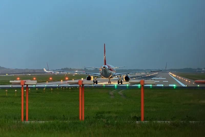
3.3 Integration with Runway Lighting: How Lights Impact RVR
Runway lighting intensity directly affects RVR readings—brighter lights make markings more visible, effectively increasing RVR in low-visibility conditions. Modern RVR systems integrate with runway lighting controls to ensure readings reflect current light intensity.
ICAO defines standard light intensity levels (1–5, with 5 being brightest) and their RVR impacts. For example:
- At Level 3 intensity, a transmissometer might measure 550 m RVR in light fog.
- Increasing lights to Level 5 could raise RVR to 700 m in the same fog, as brighter lights cut through haze more effectively.
Advanced systems—like those from Hong Kong Haisen Technology Co., Ltd.—offer automated light adjustment:
- If RVR drops below 800 meters, lights increase to Level 4.
- If RVR falls below 500 meters, lights boost to Level 5.
This automation reduces manual intervention, speeds up responses to weather changes, and ensures accurate RVR data for pilots.
4. Factors That Affect Runway Visual Range (RVR) Accuracy
RVR is not static—it fluctuates based on weather, terrain, infrastructure, and equipment performance. Understanding these factors helps airports interpret RVR data, troubleshoot issues, and ensure safe operations.
4.1 Weather: The Primary Driver of RVR
Weather is the biggest RVR influencer. Any condition that scatters or absorbs light reduces RVR, while clear weather maximizes it.
4.1.1 Fog
Fog is the most significant RVR threat, as tiny water droplets scatter light heavily. Common fog types include:
- Radiation Fog: Forms overnight when the ground cools rapidly. Dense and close to the runway, it can reduce RVR to 100 meters or less.
- Advection Fog: Forms when warm, moist air moves over cold runways (common in coastal airports). Thicker and more persistent than radiation fog, keeping RVR low for hours.
- Upslope Fog: Forms when moist air rises over hills near runways. Patchy, leading to variable RVR along the runway.
Example: London Heathrow Airport—one of Europe’s foggiest major hubs—often sees RVR drop to 200 meters in winter fog, relying on Category III operations to keep flights running.
4.1.2 Rain and Snow
Heavy rain or snow scatters light and obscures markings. Wet runways also reflect light, reducing visibility even in light rain:
- Light Rain: Reduces RVR by 20–30% (e.g., 1,000 m to 700 m).
- Heavy Rain: Cuts RVR by 50% or more (e.g., 800 m to 300 m).
- Wet Snow: More impactful than dry snow—it sticks to runways and scatters light, reducing RVR to 200 meters in minutes.
4.1.3 Dust and Smoke
Dust storms (common in arid regions like the Middle East or Southwest U.S.) and wildfire smoke drastically reduce RVR. Dust particles are larger than fog droplets, scattering light intensely—sometimes lowering RVR to 50 meters or less.
4.1.4 Wind
Wind itself doesn’t reduce RVR, but it moves weather systems (e.g., fog, rain) over the runway, causing rapid RVR fluctuations. For example, a wind gust might clear fog from the threshold (raising threshold RVR to 800 m) while midpoint RVR remains at 300 m.
4.2 Terrain and Surroundings
Airport terrain traps or disperses weather, impacting RVR:
- Valley Airports: (e.g., Denver International Airport) prone to “valley fog,” which settles in valleys and dissipates slowly—keeping RVR low for hours.
- Coastal Airports: (e.g., San Francisco International Airport) face “sea fog” (advection fog from the ocean) and salt spray. Salt corrodes RVR equipment and scatters light, lowering RVR even in mild fog.
- Airports Near Water Bodies: (e.g., Chicago O’Hare International Airport, near Lake Michigan) have higher humidity, increasing fog risk. Lake-effect fog in winter often reduces RVR to Category II thresholds.
4.3 Runway Infrastructure
Runway condition—markings, lighting, obstacles—affects pilot visibility and RVR utility:
- Markings: Clear, well-maintained markings (centerline, threshold, touchdown zone) increase “perceived RVR.” Faded or covered markings (by snow/dirt) reduce visibility, even if RVR systems report higher values. For example, faded centerlines might let pilots see only 400 meters, despite a 550 m RVR reading.
- Lighting: Dim or broken lights lower effective RVR. Airports must inspect lights daily and replace faulty bulbs immediately.
- Obstacles: Trees, buildings, or power lines near runways block pilot views, reducing effective RVR. ICAO mandates “runway strips” (clear areas around runways) to ensure unobstructed visibility.
4.4 Equipment-Related Factors
Even high-quality RVR systems produce inaccurate data without proper installation, maintenance, or calibration:
- Misalignment: Transmissometers need precise emitter-receiver alignment. A slight shift (from wind or ground movement) reduces detected light, leading to underestimated RVR.
- Dirty Lenses: Dust, dirt, or salt spray on lenses blocks light, causing false low RVR readings. Coastal airports are particularly vulnerable.
- Power Fluctuations: Unstable power reduces emitter light output, leading to false low RVR. Backup power (generators, batteries) is critical for reliability.
- Software Glitches: Outdated/corrupted software miscalculates the extinction coefficient, leading to 10–20% errors in RVR readings.
5. How to Choose the Right Runway Visual Range (RVR) System Provider
Selecting a trusted RVR provider ensures your system meets safety, regulatory, and operational needs. Use this checklist to evaluate providers:
5.1 Verify Experience and Certifications
- Proven Track Record: Ask for case studies of RVR systems installed at airports of your size/type. For example, if you run a small regional airport, request small-airport examples; if you need Category III, ask for Category III implementation stories.
- Aviation Certifications: Ensure compliance with ICAO (Annex 14), FAA (TSO C133a), EASA (CS-ENV), and local standards (e.g., CAAC for China, CASA for Australia).
- Expert Team: Confirm engineers have specialized RVR training and certifications (e.g., FAA A&P).
Red Flag: Providers that can’t share case studies or lack key certifications.
5.2 Evaluate Product Quality
- Durability: Check if equipment withstands harsh conditions: -40°C to 60°C temperatures, 150 km/h winds, and corrosion (critical for coastal airports).
- Accuracy: Verify compliance with ICAO/FAA/EASA standards (±10% accuracy for 200–1,000 m RVR). Ask for independent lab test reports.
- Innovation: Look for advanced features like AI-driven data processing (reduces noise), wireless connectivity (lowers wiring costs), or integration with weather sensors (predicts RVR changes).
Example: Haisen’s RVR systems use AI-based adaptive filtering, reducing data variability by 30% in turbulent weather for more consistent pilot readings.
5.3 Assess Customization Capabilities
- Site-Specific Design: Providers should conduct a detailed site survey to address your airport’s terrain, weather, and infrastructure. A valley airport needs a different setup than a coastal one.
- System Integration: Ensure RVR integrates with existing infrastructure (runway lighting controls, ATC systems, airport management software).
- Scalability: Can the system upgrade as your airport grows? (e.g., Category I to Category II).
Critical Question: “Can you modify the system to meet local regulations (e.g., FAA feet-based reporting or CAAC standards)?”
5.4 Review After-Sales Support
- Emergency Support: Look for 24/7 support with a <4-hour response time (critical for fog-related outages).
- Maintenance Packages: Comprehensive contracts should include regular calibration (monthly/quarterly/annual), part replacement (bulbs, filters), and software updates.
- Spare Parts Availability: Ensure 24–48-hour delivery for critical parts. Delays cause prolonged RVR outages.
Example: Haisen maintains global spare parts warehouses, delivering 95% of parts within 24 hours for urgent requests.
5.5 Compare Total Cost of Ownership (TCO)
Don’t focus solely on upfront costs—calculate TCO (upfront + maintenance + energy costs):
- Upfront Costs: Request itemized quotes (emitter, receiver, labor) and avoid hidden fees (e.g., “extra calibration costs”).
- Maintenance Costs: Ask for annual breakdowns (labor, parts). High-quality systems have higher upfront costs but lower long-term maintenance.
- Energy Costs: LED-based systems are more efficient. For example, Haisen’s LED-equipped RVR system costs $5,000 more upfront but saves $1,200/year in energy—recouping the investment in 4+ years.
5.6 Check References and Reviews
- Customer References: Ask for 3–5 references from similar airports. Call them to ask: “How reliable is the RVR system?” “How responsive is support?” “Did it meet regulations?”
- Online Reviews: Look for feedback on aviation platforms (Aviation Week, ACI World) or third-party sites (Google Reviews, Trustpilot). Watch for recurring themes (e.g., praise for support or complaints about delays).
Red Flag: Multiple negative reviews about poor support or non-compliant systems.
6. Future Trends in Runway Visual Range (RVR) Technology
RVR innovation is driven by automation, connectivity, and sustainability—helping airports adapt to climate change and growing passenger demand.
6.1 AI-Powered Predictive RVR
AI and machine learning will turn RVR from a reactive to a predictive metric:
- Visibility Forecasting: Analyze real-time weather (fog density, wind, humidity) and historical data to predict RVR 30–60 minutes in advance. Airports can proactively adjust operations (e.g., increase light intensity, notify pilots) before visibility drops.
- Self-Calibration: AI detects and corrects minor inaccuracies (e.g., dirty lenses) automatically, reducing manual calibration needs.
- Anomaly Detection: Identifies unusual RVR patterns (e.g., sudden drops) that signal system issues. Alerts maintenance staff and switches to backup mode if needed.
Example: Haisen is developing an AI RVR platform that uses 10 years of historical weather data to predict fog-related RVR drops with 85% accuracy.
6.2 IoT-Enabled Connectivity
The Internet of Things (IoT) will create a “smart airport” ecosystem for RVR:
- Real-Time Data Sharing: RVR data is sent instantly to aircraft avionics, ATC, and airport management systems. Pilots get live updates on flight displays, reducing reliance on radio communications.
- Remote Monitoring: Staff can monitor/control RVR systems via mobile apps or web dashboards—enabling faster troubleshooting, even off-site.
- UAV Integration: Drones with miniaturized RVR sensors verify ground-based readings in hard-to-reach areas (e.g., remote runways).
6.3 Sustainable RVR Systems
As airports reduce carbon footprints (per ICAO’s CORSIA initiative), sustainable RVR systems will become standard:
- Solar-Powered RVR: For remote airports with limited grid access, solar panels power emitters, receivers, and backups. Haisen is testing a solar transmissometer that operates off-grid for up to 14 days.
- Energy-Efficient Components: Next-gen LED emitters will use 50% less energy than current models. Processors will use low-power chips to cut consumption further.
- Recyclable Materials: RVR housings and components will be made from recycled aluminum/plastic and designed for easy disassembly at end-of-life.
6.4 Enhanced Durability for Extreme Weather
Climate change brings more hurricanes, blizzards, and Arctic cold—so RVR systems will be built to withstand harsher conditions:
- Hurricane-Resistant Designs: Emitters/receivers mounted on reinforced brackets that withstand 250 km/h winds.
- Extreme Cold Tolerance: Systems operate at -50°C (Arctic regions) using heated lenses and cold-resistant batteries.
- Flood Protection: Junction boxes and processors installed in elevated, waterproof enclosures.
7. Conclusion: Invest in Reliable RVR for Long-Term Aviation Success
Runway Visual Range (RVR) is more than a technical metric—it’s the foundation of safe, efficient, and compliant airport operations. For every airport, accurate RVR data ensures pilots make informed decisions, airlines avoid costly delays, and regulatory standards are met.
To maximize RVR value:
- Choose the Right System: Select a transmissometer or scatterometer aligned with your airport’s size, operational category (I/II/III), and weather conditions.
- Implement Rigorous Maintenance: Regular cleaning, calibration, and part replacement keep RVR systems reliable for 10–15 years.
- Partner with a Trusted Provider: Work with a provider with proven experience, global certifications, and 24/7 support—like Haisen—to ensure your RVR system meets current and future needs.
Investing in reliable RVR isn’t just a cost—it’s an investment in your airport’s safety, reputation, and long-term success. Contact Haisen today to learn how our AI-powered, sustainable RVR systems can elevate your airport’s operations.