If you work in aviation—whether as a pilot, avionics technician, or airline operations manager—understanding How DME Aircraft Systems Work is critical to ensuring safe, efficient flight operations. DME, short for Distance Measuring Equipment, is a foundational navigation technology that provides real-time distance data between an aircraft and a ground-based transponder, making it indispensable for everything from en-route navigation to precision approach procedures. In this in-depth guide, we’ll break down every aspect of DME aircraft systems: from their core components and step-by-step operating mechanisms to real-world applications, maintenance best practices, and future trends. By the end, you’ll not only master How DME Aircraft Systems Work but also know how to leverage this technology to enhance flight safety, reduce operational costs, and stay compliant with global aviation standards.
What Is a DME Aircraft System, and Why Does It Matter?
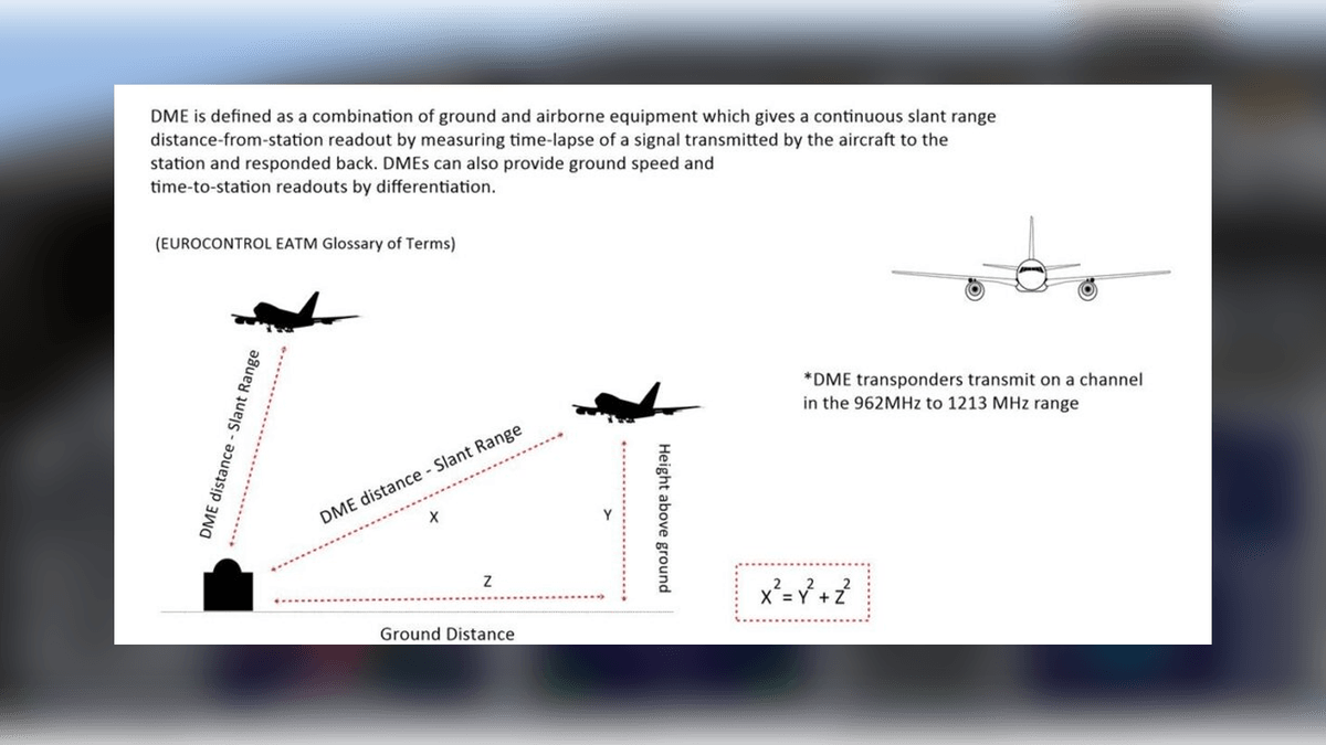
Before diving into How DME Aircraft Systems Work, it’s essential to define what a DME aircraft system is and why it remains a non-negotiable part of modern avionics. DME is a secondary surveillance radar (SSR) system that operates on ultra-high frequency (UHF) bands, working in tandem with other navigation tools like VOR (VHF Omnidirectional Range) or ILS (Instrument Landing System) to provide pilots with precise distance measurements. Unlike GPS (Global Positioning System), which relies on satellite signals, DME uses ground-based transponders—making it a reliable backup when GPS signals are disrupted (e.g., due to solar flares, jamming, or terrain blockages).
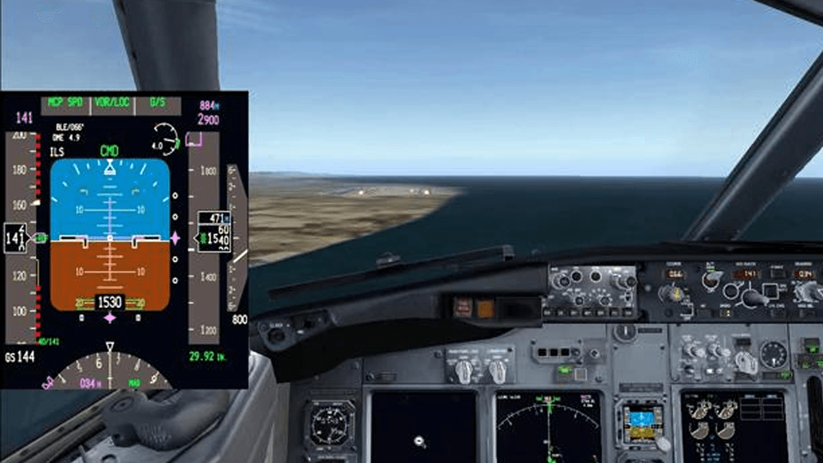
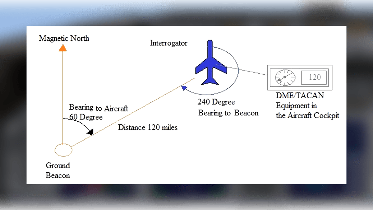
The primary function of a DME aircraft system is to calculate the slant range (the straight-line distance) between the aircraft and a DME ground station, expressed in nautical miles (nm). This data is displayed on the aircraft’s primary flight display (PFD) or navigation display (ND), allowing pilots to:
- Verify their position relative to predefined waypoints.
- Maintain safe separation from other aircraft and terrain.
- Execute accurate holding patterns, missed approaches, and en-route climbs/descents.
- Comply with air traffic control (ATC) instructions for distance-based routing.
To fully grasp How DME Aircraft Systems Work, you must first recognize that they are not standalone tools—they integrate seamlessly with other avionics to create a holistic navigation ecosystem. For example, a VOR/DME system combines the directional guidance of VOR with the distance data of DME, enabling pilots to pinpoint their location using “radial” (direction) and “distance” coordinates. This integration is why understanding How DME Aircraft Systems Work is so vital for anyone responsible for flight planning or execution.
Core Components of a DME Aircraft System: The Building Blocks
To understand How DME Aircraft Systems Work, you need to familiarize yourself with their two main components: the airborne DME unit (installed on the aircraft) and the ground-based DME transponder (stationed at airports, waypoints, or en-route locations). Each component has subparts that work in sync to transmit, receive, and process signals—let’s break them down.
The Airborne DME Unit
The airborne DME unit is responsible for initiating the signal exchange and calculating the distance to the ground transponder. It consists of four key subcomponents:
- DME Transmitter: Emits paired radio pulses (called “pulse pairs”) on UHF frequencies between 1025 MHz and 1150 MHz. These pulses are unique to DME and are designed to avoid interference with other UHF systems (e.g., ILS localizers). The transmitter adjusts its output power based on the aircraft’s altitude—higher altitude requires more power to reach distant ground stations.
- DME Receiver: Picks up the return pulses from the ground transponder, which operate on a lower UHF band (962 MHz to 1024 MHz). The receiver filters out noise and irrelevant signals, ensuring only valid DME pulses are processed.
- Signal Processor: Calculates the time delay between the transmitted pulse pairs and the received pulse pairs. This time delay is the key to determining distance—we’ll explain how this works in detail when we cover How DME Aircraft Systems Work in Section 3.
- Display Interface: Sends the calculated distance data to the aircraft’s PFD, ND, or multi-function display (MFD). Most modern systems also integrate with the aircraft’s flight management system (FMS), allowing the FMS to use DME data for automated route planning.
The Ground-Based DME Transponder
The ground-based transponder acts as a “reflector” for the airborne DME unit’s signals. It receives the aircraft’s pulse pairs, amplifies them, and retransmits them back to the aircraft with a fixed time delay (typically 50 microseconds, μs). This fixed delay is critical to How DME Aircraft Systems Work because it accounts for the time the ground station takes to process the signal—ensuring the airborne unit only calculates the time the signal spends traveling to and from the aircraft.
Ground DME transponders are classified based on their location and purpose:
- En-Route DME: Located along airways (e.g., jet routes, Victor airways) to provide distance data for long-distance navigation. These transponders have a range of up to 200 nm and are often co-located with VOR stations (forming VOR/DME sites).
- Terminal DME: Positioned near airports to support arrival and departure procedures. They have a shorter range (up to 50 nm) and are often co-located with ILS localizers or glide paths.
- Approach DME: Specifically designed for precision approach procedures (e.g., RNAV [Area Navigation] approaches). These transponders have high accuracy (±0.2 nm) and are calibrated regularly to meet ICAO (International Civil Aviation Organization) standards.
Without these two core components—airborne unit and ground transponder—How DME Aircraft Systems Work would be impossible. Their synergy ensures that distance data is transmitted, received, and processed in real time, even in harsh weather conditions or remote airspace.
Step-by-Step: How DME Aircraft Systems Work in Real Flight
Now that we’ve covered the components, let’s walk through the exact process of How DME Aircraft Systems Work during a typical flight. This step-by-step breakdown will show you how signals move between the aircraft and ground station, how distance is calculated, and how the data is presented to the pilot.
Step 1: The Aircraft Initiates a Signal Transmission
When the pilot activates the DME system (usually by selecting a DME frequency on the avionics panel—often auto-tuned if paired with VOR or ILS), the airborne DME transmitter sends a series of pulse pairs. These pulse pairs are not random: they have a specific spacing (either 12 μs or 30 μs) to identify the type of DME system (e.g., 12 μs for civilian DME, 30 μs for military DME/P) and avoid interference with other DME units.
The transmitter sends these pulses at a rate of 10 to 150 pulse pairs per second (pps), depending on the aircraft’s distance from the ground station:
- Far range (>100 nm): Lower pulse rate (10–30 pps) to conserve power and reduce interference.
- Near range (<20 nm): Higher pulse rate (100–150 pps) to provide more frequent distance updates (critical for approach and landing).
Step 2: The Ground Transponder Receives and Retransmits the Signal
The ground-based DME transponder’s receiver picks up the aircraft’s pulse pairs. It first verifies that the pulses are valid (i.e., correct frequency, spacing, and format) to filter out noise or signals from other systems. Once validated, the transponder amplifies the signal and retransmits it back to the aircraft—with a fixed 50 μs delay.
This fixed delay is a key part of How DME Aircraft Systems Work because it standardizes the ground station’s processing time. Without it, different ground stations (with varying processing speeds) would introduce errors in the distance calculation. The retransmitted pulses use a frequency that is 63 MHz lower than the aircraft’s transmitted frequency (e.g., if the aircraft sends pulses at 1050 MHz, the ground station retransmits at 987 MHz)—this frequency offset ensures the airborne receiver only picks up return signals from the ground station, not its own transmitted signals.
Step 3: The Airborne Receiver Captures the Return Signal
The airborne DME receiver monitors the lower UHF band (962–1024 MHz) for the retransmitted pulse pairs from the ground station. It uses a narrowband filter to isolate the correct frequency (matching the 63 MHz offset) and rejects any unwanted signals (e.g., from other DME ground stations or UHF radios).
Once the return pulses are captured, the receiver synchronizes them with the original transmitted pulses. This synchronization is crucial: it ensures the receiver is comparing the correct “outgoing” pulse with its corresponding “incoming” pulse, not a pulse from a later transmission.
Step 4: The Signal Processor Calculates the Slant Range
This is the “brain” of How DME Aircraft Systems Work: the signal processor calculates the time delay between the transmitted pulse pairs and the received pulse pairs. Let’s break down the math:
- Measure Total Time Delay: The processor records the time (in microseconds) from when a pulse pair is transmitted until its corresponding return pulse is received. Let’s call this T_total.
- Subtract the Fixed Ground Delay: Since the ground station adds a fixed 50 μs delay, we subtract this to get the round-trip flight time of the signal (the time it takes for the signal to travel from the aircraft to the ground and back). This is T_flight = T_total - 50 μs.
- Calculate Slant Range: Radio waves travel at the speed of light (186,000 miles per second, or 300,000 kilometers per second). To convert this speed into nautical miles per microsecond, we use the following conversion:
Since the signal travels to the ground and back (round trip), we divide the flight time by 2. The final formula for slant range is:
For example: If T_total is 650 μs, then T_flight = 650 μs - 50 μs = 600 μs. The slant range is (600 ÷ 2) × 0.1616 = 300 × 0.1616 ≈ 48.48 nm.
- 1 nautical mile (nm) = 1.1508 miles
- Speed of light = 186,000 miles/second = 186,000 / 1.1508 nm/second ≈ 161,600 nm/second
- To get nm per microsecond: 161,600 nm/second ÷ 1,000,000 μs/second ≈ 0.1616 nm/μs
Step 5: The Distance Data Is Displayed to the Pilot
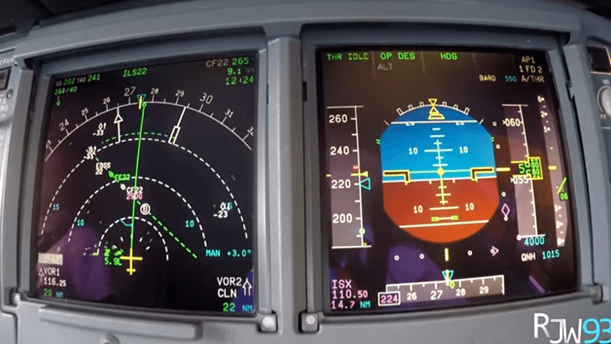
Within milliseconds, the calculated slant range is sent to the aircraft’s display interface (PFD, ND, or MFD). The data is presented in one of two formats:
- Digital Readout: A numerical value (e.g., “48.5 NM”) displayed next to the DME frequency or VOR/DME identifier (e.g., “JFK VOR/DME”).
- Graphical Overlay: On the ND, the DME distance is shown as a circular “ring” around the ground station, with the aircraft’s position marked relative to the ring. This helps pilots visualize their distance from waypoints or airports.
Most modern DME systems also provide ground speed and time-to-station (TTS) data, derived from the slant range. Ground speed is calculated by measuring how quickly the slant range changes over time (e.g., if the distance decreases by 10 nm in 5 minutes, ground speed is 120 nm/hour). TTS is calculated by dividing the slant range by the ground speed (e.g., 48 nm ÷ 120 nm/hour = 0.4 hours = 24 minutes).
This entire process—from signal transmission to display—takes less than 1 second, making How DME Aircraft Systems Work a real-time operation that keeps pilots informed with up-to-date distance data.
Key Factors That Influence How DME Aircraft Systems Work
While the basic process of How DME Aircraft Systems Work is consistent, several factors can affect the accuracy, range, and reliability of the system. Understanding these factors is critical for pilots and technicians, as they can impact flight safety and operational efficiency.
Altitude
Altitude has a significant impact on DME range. Since DME calculates slant range (not horizontal range), the higher the aircraft, the farther it can “see” a ground station. This is because the line of sight between the aircraft and ground station is less likely to be blocked by terrain (e.g., mountains, tall buildings) at higher altitudes.
The maximum range of a DME system can be estimated using the line-of-sight formula:
For example:
- At 10,000 feet: 1.23 × √10,000 = 1.23 × 100 = 123 nm
- At 30,000 feet: 1.23 × √30,000 ≈ 1.23 × 173.2 ≈ 213 nm
This is why en-route DME stations are effective for high-altitude flights, while terminal DME stations are designed for lower altitudes (e.g., during approach). Pilots must account for altitude when interpreting DME data—at low altitudes, the slant range may be slightly greater than the horizontal range (the distance along the ground), but the difference is negligible for most operations (less than 1 nm at altitudes below 5,000 feet).
Terrain and Obstacles
Terrain (e.g., mountains, hills) and man-made obstacles (e.g., skyscrapers, radio towers) can block the UHF signals used by DME systems, leading to “signal shadowing” (loss of signal) or reduced range. This is a critical consideration for How DME Aircraft Systems Work in mountainous regions (e.g., the Rocky Mountains in the U.S., the Alps in Europe) or densely populated areas (e.g., New York City, Tokyo).
To mitigate this, aviation authorities (e.g., FAA in the U.S., EASA in Europe) carefully site DME ground stations on high ground (e.g., hilltops) or near airports with unobstructed views of the surrounding airspace. Pilots are also provided with “DME coverage charts” that show areas where DME signals are reliable—these charts are essential for flight planning, especially in remote or mountainous regions.
Signal Interference
Signal interference can disrupt How DME Aircraft Systems Work by corrupting the pulse pairs transmitted between the aircraft and ground station. Common sources of interference include:
- Other DME Systems: If two aircraft are near the same ground station, their pulse pairs may overlap, causing the ground transponder to misinterpret signals. To prevent this, DME systems use “pulse coding” (unique pulse patterns) and variable pulse rates to distinguish between different aircraft.
- UHF Radio Systems: Other UHF devices (e.g., air-to-air radios, military communication systems) operating in the 962–1150 MHz band can interfere with DME signals. This is why aviation regulations strictly allocate frequencies for DME and other UHF systems.
- Atmospheric Noise: Solar flares, thunderstorms, and ionospheric disturbances can create “noise” in the UHF band, making it harder for the DME receiver to detect valid pulse pairs. Modern DME systems use error-correcting codes and signal filtering to reduce the impact of atmospheric noise.
System Calibration and Maintenance
Like all avionics, DME systems require regular calibration and maintenance to ensure they work correctly. If the airborne transmitter or receiver is out of calibration, the pulse pairs may be distorted, leading to incorrect distance calculations. Similarly, ground transponders must be calibrated every 6–12 months to maintain the fixed 50 μs delay and ensure signal accuracy.
Common maintenance tasks for DME systems include:
- Transmitter Power Checks: Verifying that the airborne transmitter outputs the correct power level (typically 10–50 watts).
- Receiver Sensitivity Tests: Ensuring the receiver can detect weak signals from distant ground stations.
- Pulse Pair Timing Calibration: Adjusting the timing of transmitted and received pulses to match ICAO standards.
- Ground Station Alignment: Ensuring the ground transponder’s antenna is pointed correctly to maximize signal coverage.
Neglecting maintenance can lead to DME errors (e.g., overestimating or underestimating distance) that could compromise flight safety. This is why understanding How DME Aircraft Systems Work also means knowing how to keep them in optimal condition.
How DME Aircraft Systems Work with Other Navigation Technologies
DME rarely operates in isolation—its true value lies in how it integrates with other navigation systems to create a robust, redundant navigation network. Let’s explore how How DME Aircraft Systems Work alongside VOR, ILS, GPS, and RNAV.
DME + VOR: The Classic Navigation Pair
VOR (VHF Omnidirectional Range) is a directional navigation system that provides pilots with a “radial” (a line of bearing) from a VOR ground station. For example, a pilot might be on the “180° radial” of a VOR station, meaning they are south of the station. But VOR alone doesn’t provide distance—this is where DME comes in.
When VOR and DME are co-located (forming a VOR/DME station), pilots can use the radial from VOR and the distance from DME to pinpoint their exact location using “radial-distance” coordinates. For example: “JFK VOR/DME 180° radial, 25 nm” places the aircraft 25 nm south of JFK Airport.
This integration is a cornerstone of How DME Aircraft Systems Work in en-route navigation. Before GPS became widespread, VOR/DME was the primary navigation method for civilian aircraft— and it remains a critical backup today. Pilots rely on VOR/DME to cross-check GPS data, ensuring they don’t stray off course due to GPS errors.
DME + ILS: Precision for Approach and Landing
ILS (Instrument Landing System) is a precision approach system that guides aircraft to the runway using two components: a localizer (horizontal guidance, left/right of the runway centerline) and a glide path (vertical guidance, high/low relative to the runway). DME is often added to ILS systems (forming ILS/DME) to provide distance data during the approach.
During an ILS approach, How DME Aircraft Systems Work helps pilots:
- Verify their position along the approach path (e.g., “5 nm from the runway threshold,” “2 nm from the decision height”).
- Maintain the correct descent rate (e.g., if the glide path indicates a 3° descent, the DME distance tells the pilot how quickly to descend to stay on path).
- Execute a missed approach if necessary (e.g., “climb to 2,000 feet when passing the 3 nm DME fix”).
ILS/DME is especially valuable for airports with poor visibility (e.g., fog, rain) where pilots can’t see the runway until close to landing. The distance data from DME ensures they stay on track and reach the decision height (DH) at the correct point.
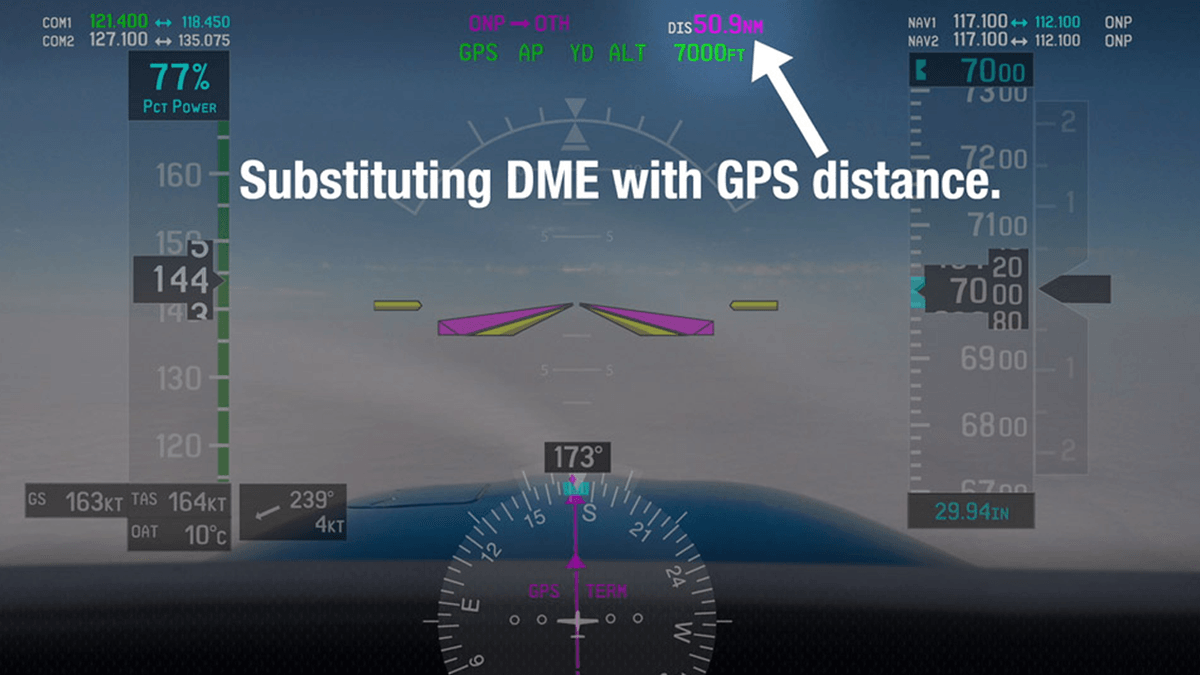
DME + GPS: Redundancy and Backup
GPS has become the primary navigation system for most modern aircraft, providing global coverage and high accuracy. However, GPS is vulnerable to signal disruptions (e.g., jamming, satellite outages), which is why DME remains a critical backup.
Understanding How DME Aircraft Systems Work alongside GPS is essential for flight safety. If GPS fails, pilots can switch to DME (often paired with VOR or ILS) to continue navigating. For example:
- During en-route flight: If GPS signal is lost, the pilot can tune to a nearby VOR/DME station and use radial-distance coordinates to stay on the airway.
- During approach: If GPS-based RNAV approach is unavailable, the pilot can switch to an ILS/DME approach to land safely.
Some advanced avionics systems even “blend” DME and GPS data to improve accuracy. For example, if GPS provides a horizontal range of 24.8 nm and DME provides a slant range of 25.0 nm, the system will use the average (24.9 nm) to reduce errors. This synergy between DME and GPS highlights why How DME Aircraft Systems Work is still relevant in the age of satellite navigation.
DME + RNAV: Flexible Route Planning
RNAV (Area Navigation) is a navigation method that allows aircraft to fly on any desired route (not just fixed airways) using a combination of navigation sources (e.g., GPS, DME, VOR). DME is often used in RNAV systems to provide distance data for “DME fixes”—predefined points in the airspace that are identified by their distance from one or more DME stations.
For example, a RNAV approach might use a “DME/DME fix” that is 10 nm from Station A and 15 nm from Station B. The aircraft’s RNAV system uses distance data from both DME stations to calculate its position relative to the fix. This flexibility makes RNAV ideal for airports with limited airspace or complex terrain—and it relies heavily on How DME Aircraft Systems Work to ensure accuracy.
Real-World Applications: How DME Aircraft Systems Work in Different Flight Phases
To fully appreciate How DME Aircraft Systems Work, let’s look at how they are used in each phase of flight: takeoff, en-route, descent, approach, and landing. Each phase has unique requirements, and DME adapts to meet them.
Takeoff and Departure
During takeoff and departure, How DME Aircraft Systems Work helps pilots comply with ATC departure procedures (e.g., “depart runway 27, climb to 3,000 feet by the 5 nm DME fix”). Here’s how it works:
- The pilot tunes to the airport’s terminal DME station before takeoff.
- After liftoff, the DME display shows the distance from the airport.
- ATC may instruct the pilot to “climb to 5,000 feet when passing 10 nm DME”—the pilot uses the DME data to know when to level off or continue climbing.
- If the departure procedure requires a turn (e.g., “turn right to heading 180° at 8 nm DME”), the pilot uses the DME distance to initiate the turn at the correct point.
DME is especially useful during departure in low visibility, where pilots can’t see visual landmarks (e.g., towers, roads) to verify their position.
En-Route Flight
En-route flight (the phase between departure and descent) is where How DME Aircraft Systems Work shines as a long-range navigation tool. Pilots use DME (often paired with VOR) to:
- Stay on airways: Airways are defined by a series of VOR/DME stations. For example, Victor Airway V25 runs from JFK VOR/DME to Chicago O’Hare VOR/DME. Pilots use the DME distance to ensure they don’t deviate from the airway.
- Maintain safe separation: ATC uses DME data to keep aircraft at least 5 nm apart horizontally (in en-route airspace). Pilots report their DME position to ATC (e.g., “JFK VOR/DME 180° radial, 30 nm”) to confirm separation.
- Plan fuel stops: DME distance helps pilots calculate how much fuel they need to reach the next airport. For example, if the next airport is 200 nm away and the aircraft burns 10 gallons per hour at 200 nm/hour, the pilot knows they need 10 gallons of fuel (200 nm ÷ 200 nm/hour = 1 hour × 10 gallons/hour = 10 gallons).
In remote areas (e.g., the Atlantic Ocean, the Sahara Desert) where GPS coverage may be limited, en-route DME stations are the primary navigation lifeline.
Descent
During descent, How DME Aircraft Systems Work helps pilots transition from en-route altitude to the airport’s terminal airspace. ATC typically provides “descent clearances” based on DME distance, such as:
- “Descend from 30,000 feet to 10,000 feet, maintaining 250 knots until passing 20 nm DME.”
- “Cross the 15 nm DME fix at 8,000 feet.”
The pilot uses the DME display to monitor their distance from the airport and adjust their descent rate accordingly. For example, if the pilot is at 30,000 feet and needs to reach 10,000 feet by 20 nm DME, they calculate a descent rate of (30,000 – 10,000) feet ÷ (time to 20 nm). If the ground speed is 300 nm/hour, time to 20 nm is 4 minutes (20 nm ÷ 300 nm/hour = 0.0667 hours × 60 minutes/hour = 4 minutes). The required descent rate is 20,000 feet ÷ 4 minutes = 5,000 feet per minute (fpm).
This precise control ensures the pilot arrives at the correct altitude at the correct point—critical for avoiding other aircraft in busy terminal airspace.
Approach and Landing
The approach and landing phase is where How DME Aircraft Systems Work is most critical for safety. Whether using an ILS/DME approach, VOR/DME approach, or RNAV/DME approach, DME provides distance data that guides the pilot to the runway:
- ILS/DME Approach: The pilot uses the localizer (horizontal) and glide path (vertical) for guidance, while DME tells them how far they are from the runway threshold. For example, the “outer marker” (a point 5–7 nm from the runway) is often marked by a DME fix, and the “inner marker” (0.5–1 nm from the runway) is another DME fix.
- VOR/DME Approach: If ILS is unavailable, the pilot uses the VOR radial to align with the runway and DME to control their descent. For example, “VOR/DME Runway 36” requires the pilot to fly the 360° radial of the VOR station and descend to 1,000 feet when passing 2 nm DME.
- RNAV/DME Approach: This approach uses DME data from multiple ground stations to create a “virtual” approach path. The pilot follows the RNAV guidance, with DME providing backup distance data.
During landing, DME also helps pilots execute a missed approach if they can’t see the runway. For example, “if no runway is in sight at the decision height (DH) of 200 feet, climb to 1,500 feet when passing the 1 nm DME fix.”
Maintenance Best Practices for DME Aircraft Systems
To ensure How DME Aircraft Systems Work reliably, regular maintenance is essential. Below are best practices for maintaining both airborne DME units and ground-based transponders, based on ICAO and FAA guidelines.
Maintenance for Airborne DME Units
Airborne DME units should be inspected and serviced every 12–24 months (depending on the aircraft type and usage). Key tasks include:
- Functional Testing: Power on the DME system and verify that it can transmit/receive signals, calculate distance correctly, and display data on the PFD/ND. This test is often done using a “DME test bench” that simulates ground station signals.
- Transmitter Power Check: Use a power meter to measure the transmitter’s output power. If the power is below the manufacturer’s specification (e.g., <10 watts), the transmitter may need to be repaired or replaced.
- Receiver Sensitivity Test: Measure the receiver’s ability to detect weak signals. A receiver with low sensitivity may not pick up signals from distant ground stations, reducing DME range.
- Cable and Connector Inspection: Check the cables and connectors between the DME unit and antenna for corrosion, damage, or loose connections. Poor connections can cause signal loss or interference.
- Software Updates: Many modern DME units have firmware that can be updated to fix bugs, improve accuracy, or add new features (e.g., integration with GPS). Ensure the firmware is up to date with the latest version.
Maintenance for Ground-Based DME Transponders
Ground-based transponders require more frequent maintenance (every 6–12 months) to ensure they meet ICAO accuracy standards. Key tasks include:
- Fixed Delay Calibration: Verify that the transponder adds exactly 50 μs of delay to retransmitted signals. If the delay is off by more than 1 μs, the transponder must be recalibrated.
- Signal Amplitude Test: Measure the strength of the retransmitted signal. A weak signal will reduce the transponder’s range, making it harder for aircraft to receive data.
- Antenna Alignment: Ensure the transponder’s antenna is pointed correctly to maximize coverage. Antennas that are misaligned may have “dead zones” where signals are weak or unavailable.
- Environmental Protection: Ground transponders are exposed to the elements (rain, snow, extreme temperatures). Check the transponder’s enclosure for water damage, rust, or debris, and clean it regularly.
- Redundancy Checks: Many ground stations have backup transponders to ensure continuity if the primary unit fails. Test the backup system to ensure it switches on automatically if the primary unit malfunctions.
Digital DME: Replacing Analog Systems
Most current DME systems use analog technology for signal processing, which is reliable but has limitations (e.g., lower accuracy, slower update rates). The future will see a shift to digital DME systems, which use digital signal processing (DSP) to:
- Improve accuracy: Digital systems can filter out noise more effectively, reducing distance errors to ±0.05 nm.
- Increase update rates: Digital DME can provide distance updates 10–20 times per second (compared to 1–5 times per second for analog systems), making it ideal for high-speed aircraft (e.g., supersonic jets).
- Reduce size and weight: Digital components are smaller and lighter than analog components, saving space and fuel on aircraft.
Digital DME will also integrate more seamlessly with other digital avionics (e.g., FMS, GPS) to create a fully connected navigation system.
DME for Unmanned Aerial Vehicles (UAVs)
The growth of UAVs (drones) for commercial and military use is driving demand for DME systems that are small, lightweight, and low-power. How DME Aircraft Systems Work for UAVs will be similar to manned aircraft, but with adaptations:
- Miniaturized components: UAV DME units will be small enough to fit on drones weighing less than 5 pounds.
- Low-power operation: UAVs have limited battery life, so DME systems will use energy-efficient transmitters and receivers.
- Autonomous integration: UAV DME will be integrated with the drone’s autopilot system, allowing it to use DME data for autonomous navigation (e.g., avoiding obstacles, maintaining waypoints).
As UAVs become more common in civilian airspace, DME will play a key role in ensuring they stay separated from manned aircraft.
DME in the Context of NextGen and SESAR
NextGen (Next Generation Air Transportation System) in the U.S. and SESAR (Single European Sky ATM Research) in Europe are initiatives to modernize air traffic management (ATM) using new technologies. How DME Aircraft Systems Work will be integrated into these initiatives in several ways:
- Performance-Based Navigation (PBN): PBN uses precise navigation data (from GPS, DME, and other systems) to allow aircraft to fly more flexible routes. DME will be a key backup for GPS in PBN, ensuring routes remain reliable even if GPS fails.
- Remote Tower Operations: Remote towers use cameras and sensors to manage airports from a distance. DME data will be integrated into remote tower displays, allowing controllers to monitor aircraft distance from the airport without being on-site.
- Data Sharing: NextGen and SESAR will enable real-time data sharing between aircraft and ATC. DME distance data will be shared via data links (e.g., ADS-B—Automatic Dependent Surveillance-Broadcast), improving situational awareness for pilots and controllers.
DME and Quantum Communication
Quantum communication is an emerging technology that uses quantum mechanics to transmit data securely (unbreakable by hackers). While still in its early stages, quantum communication could eventually be used to secure DME signals, preventing jamming or spoofing (where an attacker sends fake DME signals to mislead pilots).
How DME Aircraft Systems Work with quantum communication would involve:
- Quantum-encrypted pulse pairs: Transmitted pulses would be encrypted using quantum keys, ensuring only the intended ground station can decode them.
- Quantum sensors: Ground stations would use quantum sensors to detect fake signals, ensuring only valid DME pulses are retransmitted.
This technology is still years away, but it has the potential to make DME even more secure in an era of increasing cyber threats.
Why Mastering How DME Aircraft Systems Work Is Essential for Aviation Professionals
By now, you understand the technical details of How DME Aircraft Systems Work—but why does this knowledge matter for your career in aviation? Below are four key reasons:
Safety First
The number one priority in aviation is safety, and DME plays a critical role in keeping flights safe. Whether you’re a pilot using DME to stay on approach, a technician maintaining a DME unit, or an ATC controller using DME to separate aircraft, understanding How DME Aircraft Systems Work helps you identify and prevent errors that could lead to accidents.
For example, a pilot who knows that DME calculates slant range (not horizontal range) will avoid descending too early during an approach. A technician who understands DME signal processing will catch a calibration error before it leads to incorrect distance readings.
Compliance with Regulations
Aviation regulations (from the FAA, EASA, ICAO, and other authorities) require professionals to have knowledge of DME systems. For example:
- Pilots must pass a written exam and flight test that includes questions on How DME Aircraft Systems Work to obtain a commercial pilot license (CPL) or airline transport pilot license (ATPL).
- Avionics technicians must be certified to maintain DME systems (e.g., FAA A&P certification with avionics ratings) and must complete regular training on DME maintenance.
- ATC controllers must know how to use DME data to issue clearances and maintain separation between aircraft.
Mastering How DME Aircraft Systems Work ensures you meet these regulatory requirements and avoid fines or license suspension.
Operational Efficiency
DME systems help reduce operational costs and improve efficiency for airlines and aviation companies. For example:
- By using DME to optimize routes, airlines can reduce fuel consumption (e.g., flying a direct route using DME/DME RNAV instead of a longer airway).
- Regular DME maintenance prevents unexpected failures, reducing aircraft downtime and repair costs.
- ATC controllers use DME to manage air traffic more efficiently, reducing delays and improving throughput at busy airports.
Understanding How DME Aircraft Systems Work allows you to leverage these efficiency benefits, making your organization more competitive in the aviation industry.
Career Advancement
A strong knowledge of DME systems is a valuable skill that can help you advance your career. For example:
- Pilots who are experts in DME (and other avionics) are more likely to be promoted to captain or selected for international routes.
- Technicians who specialize in DME maintenance can move into senior roles (e.g., avionics supervisor) or work for manufacturers (e.g., designing new DME systems).
- ATC controllers who understand DME integration with NextGen/SESAR can be assigned to high-profile positions (e.g., remote tower operations, en-route center management).
In a competitive industry like aviation, mastering How DME Aircraft Systems Work sets you apart from your peers and opens up new opportunities.
Conclusion: How DME Aircraft Systems Work—A Foundation for Safe, Efficient Aviation
Throughout this guide, we’ve explored every aspect of How DME Aircraft Systems Work: from their core components (airborne unit and ground transponder) to their step-by-step operation, integration with other navigation systems, real-world applications, maintenance, and future trends. We’ve debunked myths, explained the math behind distance calculations, and highlighted why this knowledge is essential for aviation professionals.
DME may not be as “glamorous” as GPS or other modern technologies, but it remains a cornerstone of aviation navigation. Its reliability, ground-based design, and ability to work in tandem with other systems make it indispensable—whether as a primary tool in remote areas or a backup for GPS in busy airspace.
As aviation continues to evolve with digitalization, UAVs, and NextGen/SESAR, How DME Aircraft Systems Work will adapt too. But the core principle—using UHF signals to calculate distance between aircraft and ground stations—will remain the same.
Whether you’re a pilot preparing for a flight, a technician servicing a DME unit, or a student studying for a license, mastering How DME Aircraft Systems Work is an investment in your career and in the safety of the aviation industry. By applying the knowledge in this guide, you’ll be able to use DME systems with confidence, make informed decisions, and contribute to the safe, efficient operation of aircraft around the world.
If you have questions about How DME Aircraft Systems Work—or need support with DME maintenance, training, or system—don’t hesitate to reach out to our team of aviation experts. We’re here to help you leverage DME technology to achieve your goals.